Every robot needs a localization system: the ability to know its position and orientation in the environment. Robotic developers spend a lot of time iteratively improving and testing their system in different environmental conditions. In this blog post we share how the Artefacts platform can make your robotics development more efficient via two common use cases illustrated with concrete examples:
- CI-related category (e.g regression tests: tests that run automatically and include a pass/fail criteria)
- Parameter search category (e.g. tuning algorithm parameters: running many tests with different parameters to improve a metric)
Context:
- Focus on use cases relevant to many robotics platforms: robot localization
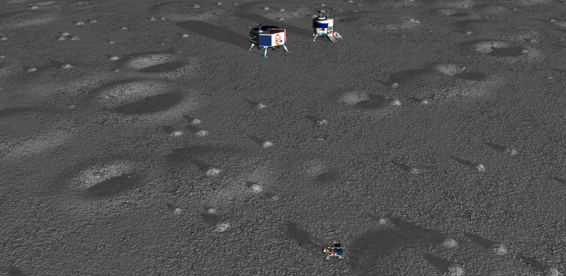
- For illustration purposes, we use a simulated environment of the lunar surface, populated with mobile robots, craters, hills and boulders.
- We use the Artefacts client with ROS1, Gazebo Classic v11 and the Artefacts Dashboard. All Artefacts related concepts showcased below are generic beyond the ROS/Gazebo/localization example taken here and are meant to be applied to a wide range of use cases.
Each example below includes the test rationale + test description + test results, with clear guidance on how to use Artefacts to enable them. Special care is taken to keep the implementation specifics to a minimum. For additional implementation details see the reference tutorial based on ROS1 and turtlesim.
Category 1: Regression Test Example:
Rationale:
Regression tests are best practice for any complex system: define tests to ensure any already implemented capability is not degraded by subsequent developments.
Test Description:
We define our example regression test such that:
- the robot mobility tech stack is activated (control of the four wheel actuators and four steering actuators)
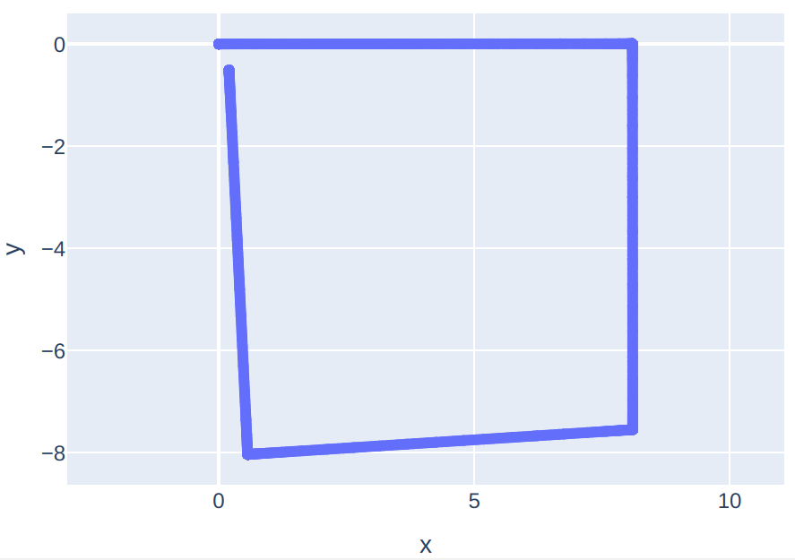
- the robot is tasked to perform a square trajectory (start at coordinates [0, 0], then drive for 4 equal length straight traverses and 3 spot turns)
- the success criteria is that the final position of the rover is near the start position (the loop trajectory is complete)
Test Setup:
-
The code for the test is written according to the ROS
rostestconventions. Here we assume that the test commands have been written in thetest_loop.launchfile of thetestingROS package in your ROS workspace. See the documentation on writing rostest tests -
Create the
artefacts.yamlfile at the root of your repository by following the configuration file syntax documentation. It can be as simple as:project: demo-space-robotics jobs: rover_trajectory: type: test runtime: simulator: gazebo:11 framework: ros1:0 scenarios: settings: - name: regression_test_loop ros_testpackage: testing ros_testfile: test_loop.launch -
Then, executing this test can be done in any of three ways:
- locally for development/testing:
artefacts run rover_trajectory - remotely on the Artefacts infra:
artefacts run-remote rover_trajectory - best for CI use cases: automatically on the Artefacts infra, tests will run on every future push to the repo: (link the repository with the Artefacts Dashboard).
- locally for development/testing:
Take-away
This test will make sure that regardless of the next features any developer implements, the core mobility functionality of the robot is not degraded.
This concept holds true for all important functions of a complex system. During development of a typical robotics project, tens (or hundreds!) of such regression tests are written and periodically executed. Artefacts makes defining, automatically executing and logging the results as easy as adding scenario entries into the artefact.yaml file.
Category 2: Parameter Tuning Grid Search Example:
Rationale:
Traditionally, parameter tuning in robotics is time consuming and error prone because:
- the parameter search space is large, requiring running many tests iteratively. Manually setting up each test, monitoring it and checking the results is tedious and time consuming.
- keeping track of test results and ensuring repeatable test conditions manually is tedious and error prone.
Artefacts provides a framework to specify each aspect of the test, parameterize it and perform a grid search across sets of parameters automatically while logging all results and displaying them in a central Dashboard.
Test description:
Tuning the covariance matrix of sensor outputs needed for Kalman filters is often empirical and iterative. Datasheets usually provide orders of magnitude for noise levels but significant performance gains are obtained by adjusting covariance parameters to one’s application.
In this example we are using an Extended Kalman Filter to fuse IMU and Wheel Odometry data. Our goal is to improve the localization accuracy of the robot. Precisely, we want to minimize three metrics: horizontal error final, vertical error final and orientation error final.
We assume that the covariance matrix of the IMU is fixed. We need to tune the covariance matrix of the Wheel Odometry, six parameters:
- linear velocity on x (forward/backward), y (left/right) and z (up/down)
- angular velocity on x (roll), y (pitch) and z (yaw)
Our robot is a four wheel, holonomic platform. To reduce the number of parameters and avoid combinatorial explosion we assume identical covariance for x and y axis. With a total of 4 tunable parameters, testing 3 values for each parameters already leads to 81 combinations. This would be intractable with a traditional / manual test setup! But we can configure this easily with Artefacts then let the tests run during lunch and check the results on the Dashboard afterwards.
Test setup:
To allow Artefacts to run tests and vary parameters for us we need to:
- add a parameter interface between our codebase and Artefacts. For example, this could be checking the ROS
rosparamserver at the beginning of a node’s execution. At the beginning of each test, each parameter passed toartefacts.yamlwill be made available on the rosparam server by Artefacts. - add the parameters themselves to
artefacts.yamlas a list. They will serve as the basis for the automatic grid coverage implemented by Artefacts: every combination of parameters will trigger a test scenario. For example, the simple .yaml below has the power to create \(3^4 = 81\) test scenarios!project: demo-space-robotics jobs: rover_trajectory: type: test runtime: simulator: gazebo:11 framework: ros1:0 scenarios: settings: - name: trajectory ros_testpackage: testing ros_testfile: test_odometry.launch subscriptions: pose: small_scout_1/ground_truth_pose result: small_scout_1/rover_odometry camera: small_scout_1/camera/left/image_raw/compressed monitoring_camera: monitoring_camera/top_down/image/compressed rosbag_record: subscriptions # choose between : all, none, subscriptions rosbag_postprocess: trajectory_post_process.py params: cov_lin_vel_xy: [0.00000005, 0.0000005, 0.000005] cov_lin_vel_z: [0.0000000005, 0.000000005, 0.00000005] cov_ang_vel_xy: [0.0001, 0.001, 0.01] cov_ang_vel_z: [0.0001, 0.001, 0.01]
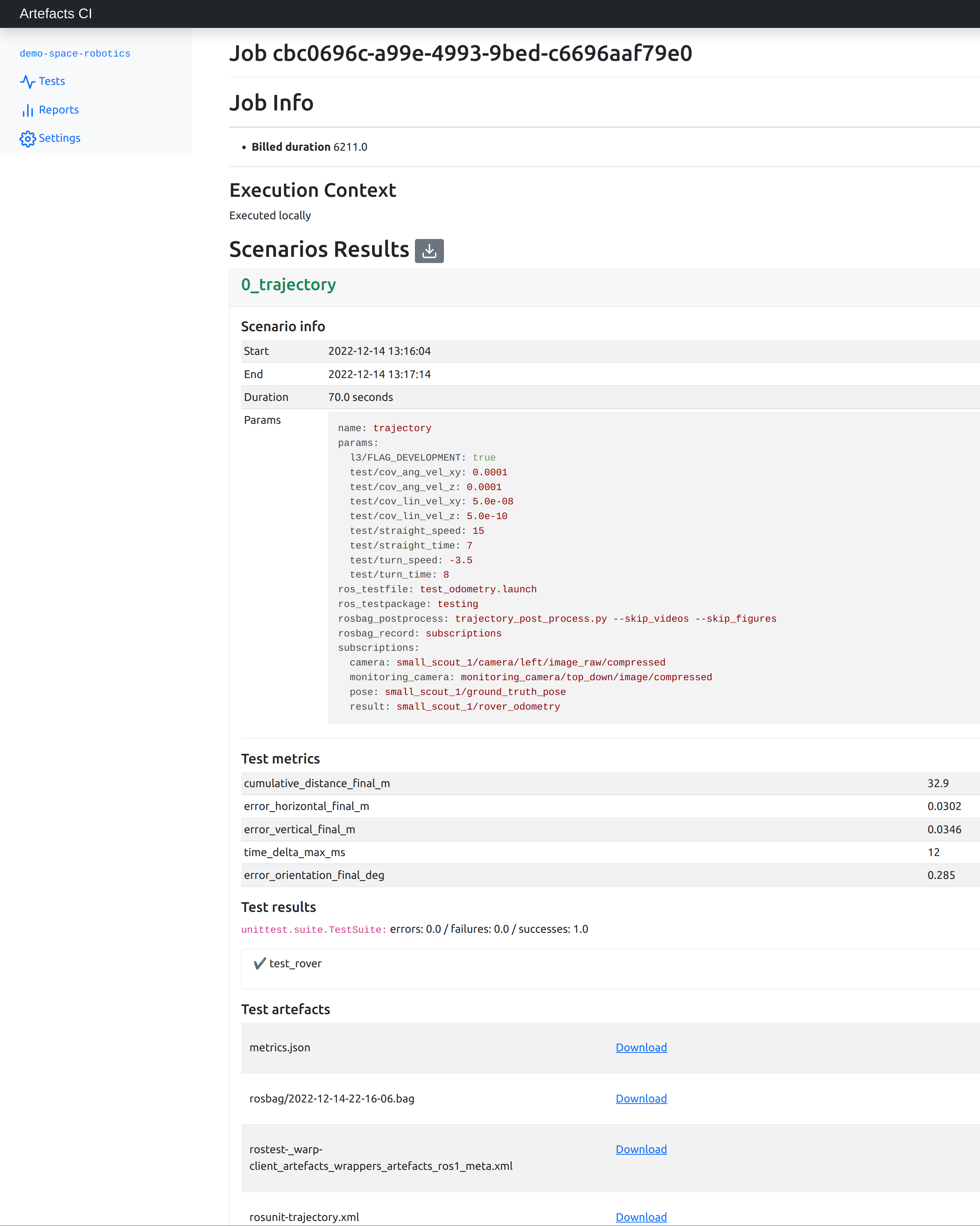
Test Results:
The results from each and every test are available on the Artefacts Dashboard. There, a convenience button allows downloading the aggregated metrics from all scenarios into a CSV.
From the CSV, we plot the three metrics of interest for each scenario:
Here lower values are better and the goal is that all three metrics are minimized jointly.
To make comparing results across the three metrics more practical, it is common practice to define a figure of merit :
\(FoM = \displaystyle\sum_i w_i * m_i\) where each \(w_i\) is the weight assigned to each metric \(m_i\)
These weights should be chosen according to the goals of the project (is it more important to minimize orientation error or horizontal error?) Here we choose that 1 deg of orientation error is equivalent to 10 cm of horizontal/vertical error. Then we plot the figure of merit for each of the 81 scenarios:
We can then rank each scenario:
Scenario 10 minimizes the figure of merit: we now have the best set of parameters to input to the Kalman filter.
Take-away
The Artefacts platforms provides the capabilities to :
- specify target values for parameters of interest
- automatically orchestrate running arbitrarily large number of tests (here 81 tests)to check for all combinations of parameters
- centrally log the results for each test in the Artefacts Dashboard
- download all the metrics as a CSV
Conclusion
These capabilities significantly speed up iterative development and fine tuning tasks that are common during robotics development. The examples above provide a reference recipe that can be adapted to any other use case that benefits from orchestrating tests, such as:
- tuning PID gains
- localization performance on other trajectories, such as going into craters and over hills
- compare the performance of several control or localization frameworks
- randomizing simulated environment parameters
- collecting datasets for Machine Learning